AFRY's Approach to VDC|BIM in Hydropower
AFRY's standard approach with VDC|BIM
AFRY has developed a standard approach of how to apply VDC|BIM in daily engineering work. It has been successfully implemented in several infrastructure and energy projects. Generally, new hydropower projects in Switzerland designed by AFRY are executed with this approach only.

AFRY's approach is based on five main columns
- Goals and added value
- 1. Sub-models in IFC standard
- 2. Synchronized model updates
- 3. Software-based issue management
- 4. Collaboration workshops (ICE Sessions)
- 5. Sequential design process

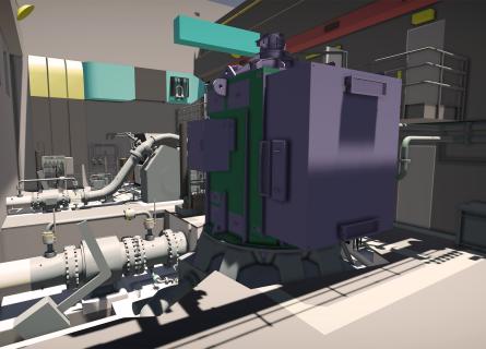
Working with sub-models in IFC standard
Each party participating in the design coordination process is responsible for the sub-models representing their scope. There is no overall model that covers the entire structure. Rather, the various sub-models are displayed assembled together in a viewer, e.g. BIMcollab Zoom.
Hence, there is no copying and pasting of partial models into an overall model, and no dilution of responsibilities. The responsibilities for each model are clearly defined. There is also no coordination in native formats. All sub-models are IFC-exports from the software programs of the different designers.
Apart from newly planned elements, sub-models can also visualize basic information. Existing structures are captured with laser scans, terrains are modelled as digital terrain models (DTM) based on drone survey campaigns, water levels are modelled, and geological surfaces are modelled in 3D. These are then converted into IFC-standard sub-models.

Synchronized model updates on a weekly basis
The model is updated on a weekly basis throughout the design phase. On a specific day of the week, all parties involved upload their current design status to the cloud. From this moment on, the updated sub-models are available to all other participants. The outdated models are archived, which ensures the traceability of changes.
Structures grow and get more detailed as they are developed together with the client, designers, equipment suppliers and the civil contractor.
In the first part of the coordination phase, the focus is on the joint development and optimization of a structure. The arrangement and design of the equipment, the static requirements of the civil structure, the requests of the client and the requirements for the execution are coordinated. In the second part of the coordination phase, the focus is on optimization of details and resolving collisions. The first step is done visually and the second step is automated. The attributes stored in the models, such as the name of the equipment, material of pipes, purpose of embedded parts or type of concrete, support the coordination.

Software-based issue management
Specialized coordination software, e.g. BIMcollab Zoom, allows the recording and management of so-called “issues”, which include collisions, change requests and other problems.
Parallel to the scheduled model updates, these issues are processed and updated by communicating adjustments to the models or suggesting alternative solutions. All parties involved in an issue must then check and approve the solution in the models before the issue is closed.

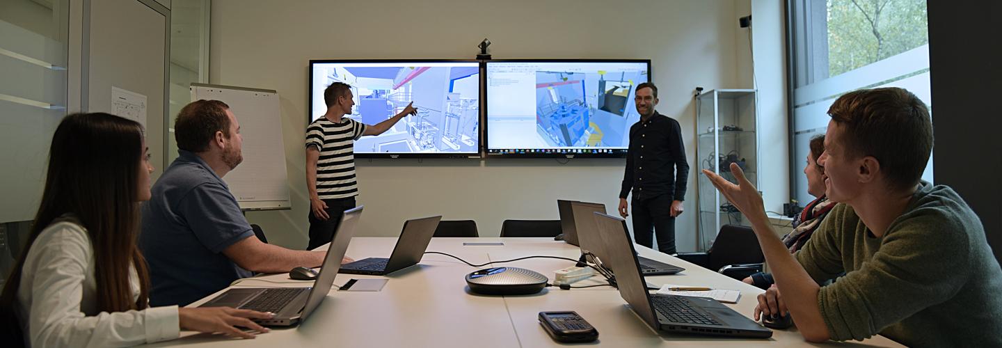
Collaboration workshops (ICE Sessions)
While simpler issues are discussed and resolved using issue management software, the more complex ones are dealt with by ICE Sessions (Integrated Concurrent Engineering). All parties involved are present at the ICE Sessions, and advantages and disadvantages of proposed solutions can be directly and efficiently discussed. Quite often new ideas emerge which lead to improved solutions.
ICE Sessions work with the concept of design sprints, known from software development. Common work alternates with coordinated individual work. The purpose of ICE Sessions is problem solving and decision making, hence milestones are never reached during ICE Sessions. ICE Sessions need proper preparation, the various preparation and postprocessing steps usually cover one week.
After this week the issues discussed at the ICE Session are usually resolved, the respective sub-models are updated and the solutions are ready to be visually checked by all parties involved.
Sticking to a sequential design process
In hydropower, some designers come on board after tendering only. This is different than in other infrastructure projects.
With VDC|BIM, a coordination phase is introduced before the start of the detail design of suppliers and civil design engineers. The aim of the coordination phase is to ensure that all interfaces between structures and equipment are coordinated. At the end of the coordination phase, the concrete outlines of the civil structures, including all block-outs and embedded parts, are finalised.
In a classical coordination setup, detail design of suppliers and civil design engineers often start directly after the tendering phase, without proper coordination.
Only after the coordination phase has been completed, does the detailed design by suppliers and civil design engineers begin. For example, executing detailed structural calculations and creating reinforcement models.


Interested in our offering? Contact us!